Free AI Engineering Blueprint Generator - Create Technical Drawings
Generate professional engineering blueprints and technical drawings instantly with AI. Free blueprint generator powered by Nano Banana Pro. Create CAD-style schematics, mechanical drawings, and technical diagrams in seconds. Perfect for engineers, students, and technical documentation.
1. What is Engineering Blueprint Generator?
The Engineering Blueprint Generator is a specialized AI-powered tool designed to transform textual descriptions into professional-grade technical drawings, CAD-style schematics, and engineering blueprints. Powered by the advanced Nano Banana Pro model, it bridges the gap between conceptual ideation and technical visualization, allowing engineers, product designers, and students to generate precise mechanical diagrams in seconds.
Unlike generic image generators that struggle with straight lines and geometric consistency, the Engineering Blueprint Generator is fine-tuned to understand the visual language of engineering. It replicates the aesthetic of traditional cyanotypes (blueprints) and modern CAD exports, making it an invaluable asset for creating rapid prototypes, technical documentation illustrations, and educational materials. Whether you need an exploded view of a gearbox or a schematic of a circuit board, this tool interprets technical terminology to deliver structurally plausible and visually authentic results.
7 Key Features
- Technical Line Precision: The core strength of the generator lies in its ability to render crisp, unwavering lines essential for technical drawings. It distinguishes between object lines, hidden lines, and center lines, maintaining high contrast and clarity typical of vector-based CAD software.
- Dimension Annotations: It automatically populates drawings with dimension lines, arrows, and numerical values. While these are primarily for visual reference and layout planning, they accurately mimic industry-standard dimensioning styles (ANSI/ASME Y14.5).
- Multiple Projection Types: The tool supports various standard projection methods including orthographic projections (front, top, side views), isometric views for 3D representation, and perspective technical illustrations, providing comprehensive visualization options.
- Material Call-outs: It can generate leaders and call-out text to indicate materials (e.g., "Aluminum 6061", "Polycarbonate"), surface finishes, or specific component names, aiding in the creation of communicative instructional diagrams.
- Assembly & Exploded Views: For complex mechanisms, the generator can visualize assembly views showing how parts fit together, or exploded views that displace components along an axis to reveal internal ordering and relationships.
- Cross-section Capabilities: Users can request cross-sectional views (cutaways) to reveal internal geometries, wall thicknesses, and hidden mechanisms that are not visible in standard exterior views.
- Industry Standard Formatting: The output respects the aesthetics of professional engineering documentation, often including drawing borders, title block placeholders, and standard schematic symbols, making the images ready for insertion into technical reports or presentations.
2. How to Use Engineering Blueprint Generator?
Creating technical drawings with AI requires a structured approach to ensure the output meets engineering standards. Follow this step-by-step workflow to generate high-quality blueprints.
Step 1: Describe Your Technical Drawing
The quality of your blueprint depends heavily on the specificity of your prompt. You must define the object, the type of view, and the drawing style.
- Component/Assembly: Clearly state what the object is (e.g., "planetary gear system," "hydraulic check valve").
- View Type: Specify if you need an isometric view, top-down plan, or cross-section.
- Style: Use terms like "blueprint style," "white on blue," or "black and white technical line drawing."
Example Prompt:
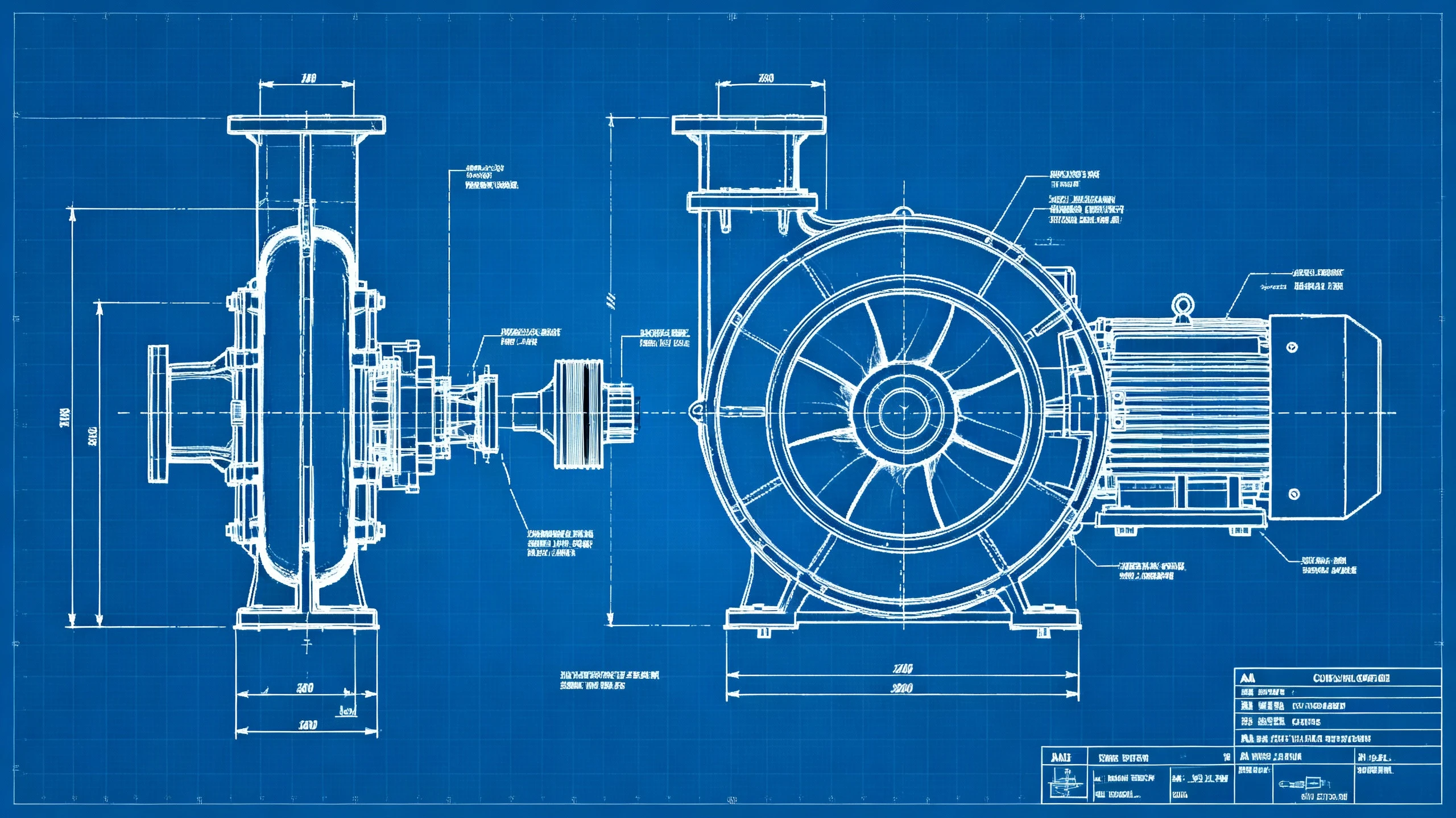
"Technical engineering blueprint of a centrifugal pump assembly, exploded view showing impeller and casing. White lines on classic blue background. CAD style, detailed dimension lines, material annotations, high contrast, clean distinct lines, ANSI standard drawing format."
💡 Pro Tips:
- Specify Projection: Always clarify if you want 2D orthographic or 3D isometric.
- Dimensioning Style: Add "with measurement annotations" or "dimension lines" to populate the drawing with technical markers.
- Material Specs: Mention textures if needed, e.g., "hatched cross-section for cast iron."
- Line Weight: Request "variable line weights" to distinguish between outlines and detail lines.
- Scale: While AI doesn't draw to exact scale, adding "scale indicator" can prompt the generation of a reference scale bar.
Step 2: Parameters
Configure the generator settings to optimize for technical imagery.
- Models: Select Nano Banana Pro (gemini-3-pro-image-preview) for engineering blueprint generation. This state-of-the-art AI model has superior understanding of technical geometry, precise line rendering, and text annotation compared to general-purpose models, ensuring straight lines, clear dimension labels, and accurate technical symbols. SeeDream AI is a viable alternative for cleaner, less textured schematic diagrams and simplified technical illustrations with minimal noise.
- Size:
- Landscape (16:9 or 3:2): Best for standard wide blueprints, complex assemblies, and layouts that include a title block.
- Square (1:1): Suitable for detailed spot views of individual components or fasteners.
- Negative Prompt: Essential for cleaning up the drawing. Use terms like: photorealistic, shading, color, gradient, organic shapes, blurry, messy lines, 3d render.
Step 3: Generate & Use in Documentation
Once generated:
- Review: Check the structural logic and clarity of the lines.
- Download: Save the image in high resolution.
- Post-Processing: For final documentation, you may want to overlay precise text labels using an image editor, as AI-generated text can sometimes be pseudo-text.
- Export: Integrate the image into technical manuals, patent disclosures (as reference), or engineering presentations.
3. Use Cases & Prompts
Engineering blueprints serve diverse industries and applications. This section explores real-world scenarios where AI-generated technical drawings provide the most value, along with ready-to-use prompt examples.
3.1 Product Design & Development
Designers and engineers use blueprints to communicate product concepts to stakeholders, manufacturers, and clients before investing in expensive prototyping.
Application: Concept validation meetings, pitch decks, crowdfunding campaigns, initial design reviews.
Example Prompt:
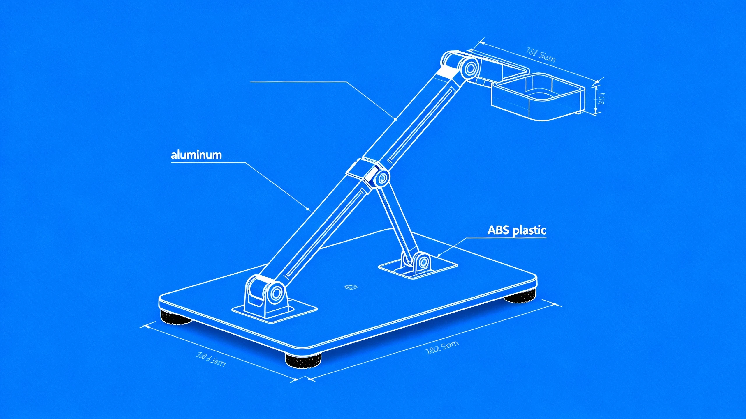
Technical blueprint of a foldable laptop stand, isometric exploded view. Showing base plate, adjustable arm, hinge mechanism, rubber feet. White lines on blue background, material callouts (aluminum, ABS plastic), dimension lines, engineering drawing style.
3.2 Technical Documentation & Manuals
Service manuals, maintenance guides, and assembly instructions require clear technical illustrations to help technicians understand component relationships and repair procedures.
Application: User manuals, service documentation, training materials, troubleshooting guides.
Example Prompt:
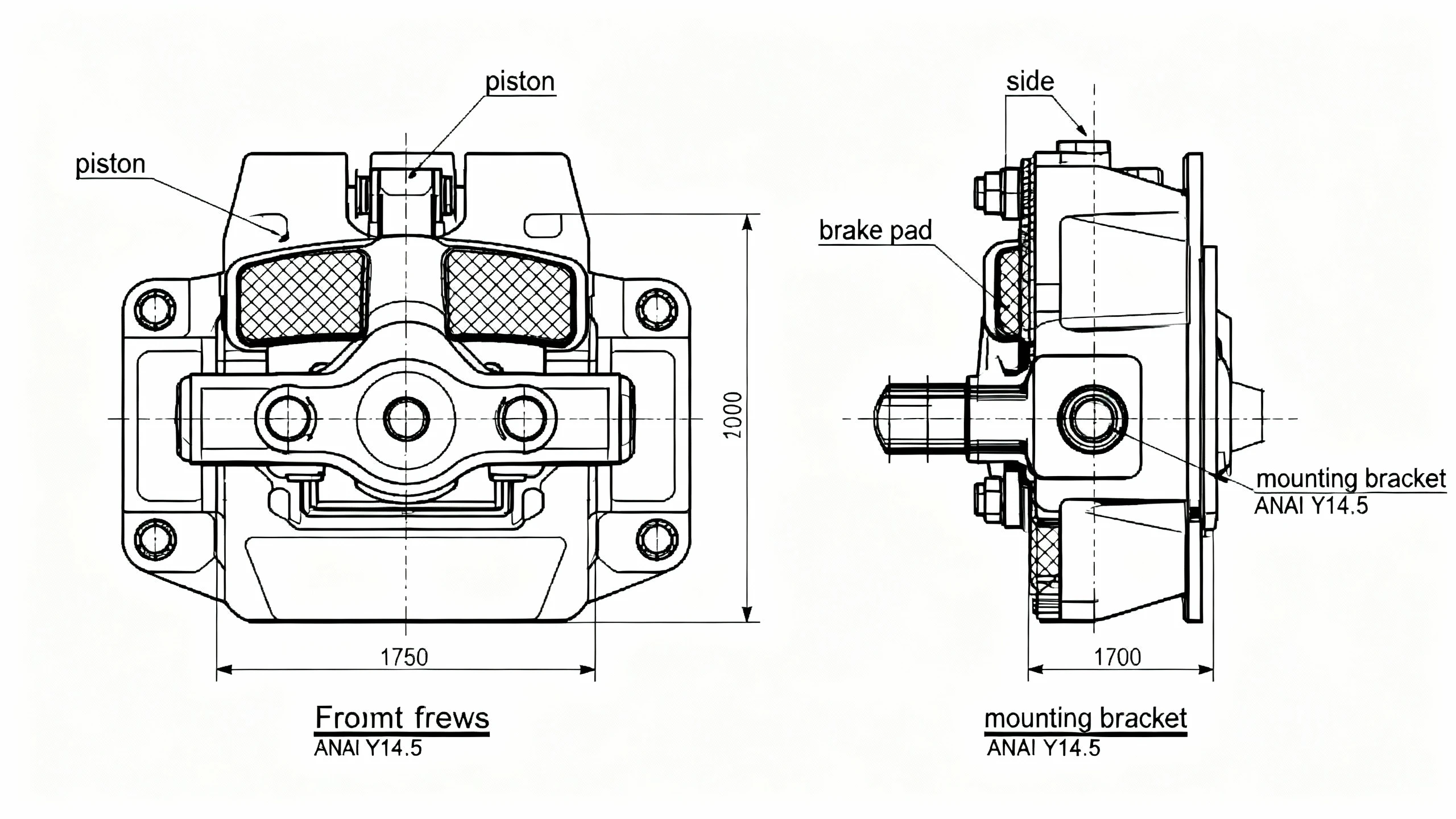
Orthographic technical drawing of an automotive brake caliper assembly, front view and side view. Black lines on white background, labeled components (piston, brake pad, mounting bracket), cross-hatching for metal parts, detailed annotation lines, ANSI Y14.5 dimensioning.
3.3 Patent Applications & IP Documentation
Inventors need clear technical illustrations for patent applications to demonstrate novelty and functionality of their innovations.
Application: Provisional patents, utility patents, design patents, intellectual property portfolios.
Example Prompt:
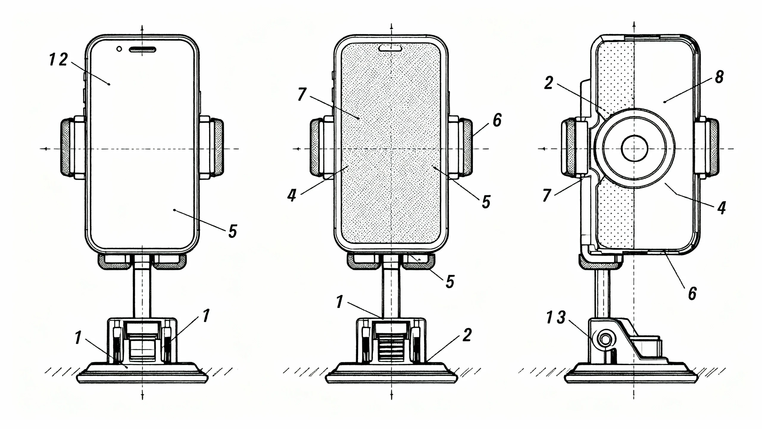
Patent drawing style illustration of a magnetic phone mount mechanism, multiple views (front, side, top, isometric). Clean black line art on white, cross-section view showing internal magnet placement, numbered component references (1-8), stippling shading, USPTO compliant format.
3.4 Educational Materials & Training
Educators and instructional designers use technical drawings to teach engineering principles, mechanical systems, and technical literacy.
Application: Textbooks, e-learning platforms, technical training courses, STEM education.
Example Prompt:
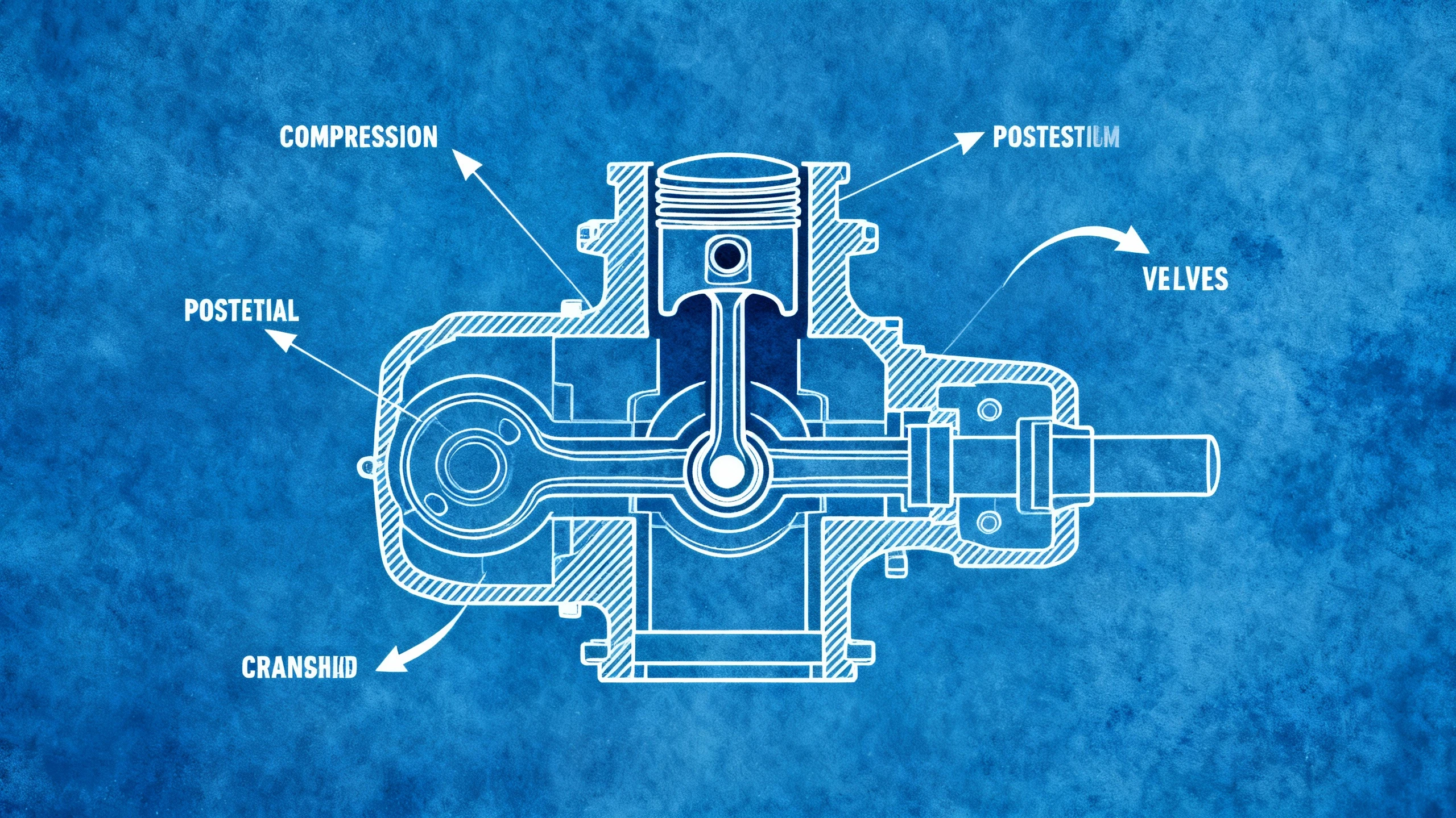
Educational cross-section diagram of a four-stroke internal combustion engine, cutaway view showing piston at compression stroke. White lines on blue cyanotype background, labeled parts (cylinder, piston, valves, crankshaft), directional arrows, simplified technical illustration style.
3.5 Architecture & Construction
Architects and contractors use technical drawings for floor plans, structural details, and construction specifications.
Application: Building permits, construction documents, renovation plans, structural engineering.
Example Prompt:
Architectural blueprint of a residential staircase, side elevation view with structural details. White lines on blue background, showing treads, risers, stringers, handrail mounting points. Dimension annotations, material specifications (wood, steel), scale indicator 1:20.

4. Prompt Writing Guide
Mastering blueprint generation requires understanding the specific vocabulary and structural conventions of engineering documentation. This comprehensive guide provides the framework for creating professional technical drawings.
4.1 Blueprint Prompt Structure
A well-structured prompt follows this proven formula:
[Drawing Type] + [Subject] + [View/Projection] + [Components] + [Style/Format] + [Annotations] + [Technical Specs]
Template Example:
[Technical blueprint] of [centrifugal pump], [exploded isometric view], showing [impeller, casing, shaft, seals], [white lines on blue background], [dimension lines, material callouts], [CAD style, high contrast, ANSI standard].
4.2 Essential Blueprint Keywords
These keywords are critical for triggering the AI to generate proper technical drawings:
Drawing Types:
- "Technical blueprint", "engineering drawing", "mechanical schematic", "CAD illustration"
- "Technical line drawing", "industrial design schematic", "assembly diagram"
Projection Methods:
- "Orthographic projection" (front, top, side views)
- "Isometric view" (30-degree 3D angle)
- "Exploded view" (components separated along axis)
- "Cross-section" or "cutaway view" (internal reveal)
- "Detail view" (close-up of specific feature)
Visual Style:
- "White lines on blue background" (classic cyanotype)
- "Black lines on white background" (modern CAD)
- "Blueprint style", "cyanotype aesthetic"
- "Clean line art", "vector style drawing"
4.3 Annotation & Dimensioning
Control how the AI adds technical information to your drawings:
Dimension Elements:
- "Dimension lines", "measurement annotations", "size callouts"
- "Leader lines", "reference numbers", "part labels"
- "Material specifications", "surface finish notes"
- "Scale indicator", "drawing scale 1:10"
Standard Compliance:
- "ANSI Y14.5 standard", "ISO dimensioning"
- "Engineering drawing conventions", "technical drafting standards"
4.4 Line Types & Conventions
Line Weight & Style:
- "Variable line weights" (thick outline, thin details)
- "Hidden lines" (dashed for obscured features)
- "Center lines" (dash-dot for symmetry axes)
- "Section lines" or "hatching" (indicate cut surfaces)
Example: "Technical drawing with variable line weights, thick object lines, dashed hidden lines, center lines for rotational symmetry."
4.5 Material Representation
Cross-Section Patterns:
- "Cross-hatching for steel parts"
- "Stippling for cast iron"
- "Diagonal lines for aluminum"
- "Brick pattern for masonry"
Material Callouts:
- "Material annotations: aluminum 6061, stainless steel 304"
- "Surface finish callouts: anodized, powder coated"
4.6 Negative Prompts for Blueprints
Exclude these elements to maintain technical drawing purity:
Photorealistic, 3D render, shading, gradient, color (except blue/white or black/white), organic textures, artistic style, painterly, sketch, hand-drawn, irregular lines, blurry, low resolution, messy lines, watermark, text artifacts, perspective distortion.
4.7 Advanced Techniques
Multi-View Drawings:
Orthographic projection of [object], showing front view, top view, right side view. Third-angle projection, aligned views, projection lines connecting features, ANSI standard layout.
Assembly Sequences:
Step-by-step assembly diagram of [device], showing 4 sequential stages. Isometric view, numbered steps, directional arrows, exploded components in each stage, assembly instruction style.
Detail Callouts:
Main view: [overall assembly]. Detail A: enlarged view of [specific joint/connection] at 2x scale. Leader line connecting detail to main view, clean technical illustration.
Additional Blueprint Examples
Mechanical Assemblies - Gear Systems:
Mechanical engineering blueprint of a planetary gear system, orthographic projection showing front view and side view. White lines on blue background, dimension annotations, gear teeth details, center lines, technical drawing style, precise geometric shapes.

Cross-Section Views - Hydraulic Systems:
Engineering cross-section blueprint of a hydraulic cylinder, cutaway view showing internal piston and seals. White lines on classic blue cyanotype background, material callouts, dimension lines, hatching for metal parts, technical CAD style.

Electrical Schematics - Wiring Diagrams:
Electrical wiring schematic of a three-way switch circuit, showing power source, switches, and light fixture. Clean line drawing style, standard electrical symbols, labeled components, black lines on white background, technical diagram.

5. Engineering Blueprint FAQs
Q1: Can AI-generated blueprints replace professional CAD software?
No. AI blueprint generators are visualization and concept tools, not replacements for precision engineering software like AutoCAD, SolidWorks, or CATIA. Professional CAD software is essential for:
- Exact dimensional accuracy and tolerances
- Parametric modeling and design iterations
- Engineering calculations and simulations
- Manufacturing file exports (G-code, CNC paths)
- Legal documentation and certification
Use AI generators for rapid prototyping, educational illustrations, patent concept sketches, and technical communication. For production engineering, always rely on professional CAD.
Q2: How accurate are the dimensions shown in AI-generated blueprints?
AI-generated dimension annotations are illustrative, not exact. The numbers and dimension lines are part of the aesthetic to make the drawing look like a blueprint, but they:
- May not correspond to actual pixel measurements
- Are not parametrically linked to geometry
- Cannot be relied upon for manufacturing
If you need exact dimensions, create the blueprint in CAD software or manually annotate the AI output in vector editing software (Adobe Illustrator, Inkscape) with precise measurements.
Q3: Are these blueprints compliant with ANSI, ISO, or DIN standards?
AI generators approximate standard conventions but don't guarantee compliance. They understand:
- General visual language (line types, projection methods)
- Common symbols and annotations
- Typical blueprint aesthetics
For legal compliance (patent applications, building permits, manufacturing specs), you must:
- Verify all standards manually
- Use certified CAD software
- Have drawings reviewed by licensed engineers
AI blueprints work for presentations, education, and conceptual communication—not regulatory submissions.
Q4: Can I add custom text and annotations to AI-generated blueprints?
Yes, but with limitations. AI-generated text can be:
- Pseudo-text (looks like text but isn't editable)
- Slightly distorted or illegible at small sizes
- Inconsistent in font and placement
Best practice: Generate a clean base drawing with minimal text, then add precise annotations in post-processing:
- Import the AI image into Photoshop or GIMP
- Add text layers with proper engineering fonts (e.g., "ISO 3098" style)
- Use vector software for crisp, scalable annotations
- Export as high-resolution PDF for printing
Q5: How do I create a full assembly drawing with multiple parts?
For complex assemblies:
- Generate individual part blueprints separately (one prompt per component)
- Use consistent style keywords across all generations
- Assemble in layout software (Adobe InDesign, Affinity Publisher, or CAD)
- Add assembly callouts and bill of materials manually
Alternatively, prompt for a complete exploded view: "Isometric exploded assembly drawing of [device], showing [part A], [part B], [part C] separated vertically, with leader lines and part numbers."
Q6: Can I generate patent drawings with AI?
Yes, for provisional or early-stage concept patents. AI can create:
- Isometric views of inventions
- Exploded assembly views
- Cross-sectional diagrams
- Detail callouts
However, utility patent drawings submitted to USPTO/EPO must meet strict requirements:
- Exact line weights and hatching patterns
- Specific margins and title blocks
- No shading (only line drawings)
- Professional drafter certification in some cases
Use AI for internal brainstorming and provisional filings, but hire a patent illustrator for final submissions.
Q7: How do I ensure consistent scale across multiple blueprint generations?
AI doesn't maintain absolute scale between generations. To create consistent sets:
- Use identical framing language: "centered in frame," "fills 80% of canvas"
- Generate at same resolution: stick to one aspect ratio
- Manually scale in post: import all images into CAD or Illustrator, scale to common reference dimension
- Add scale bars: prompt for "1:10 scale bar in corner"
For precise work, always overlay AI outputs on a calibrated CAD grid.
Q8: Can I create wiring diagrams and electrical schematics with AI?
Yes, AI can generate:
- Circuit board layouts (PCB top views)
- Wiring harness diagrams
- Electrical schematic symbols
Example prompt: "Electrical wiring schematic of a three-way switch circuit, showing power source, switches, and light fixture. Clean line drawing style, standard electrical symbols, labeled components."
Limitation: AI doesn't understand electrical logic or validate circuit functionality. Use specialized software (KiCAD, Eagle, Altium) for functional circuit design. AI is best for illustrative or educational schematics.
Q9: What file formats should I use for different purposes?
- For presentations/reports: High-res PNG (lossless, supports transparency)
- For printing: PDF (vector-friendly, maintains quality at any size)
- For web documentation: JPEG (smaller file size, fast loading)
- For further editing: TIFF (uncompressed, high quality, layered)
- For vector conversion: SVG (trace AI output in Illustrator for scalable graphics)
Always generate at the highest resolution available, then downscale as needed.
Q10: How can I use AI blueprints in educational settings?
AI blueprints are excellent teaching tools:
- Engineering students: Visualize orthographic projection concepts without mastering CAD
- Trade schools: Create assembly instructions for hands-on training
- Textbook illustrations: Rapidly generate technical diagrams for publications
- Online courses: Produce consistent visual aids across modules
Educational use case: Generate a series of "How it works" diagrams (e.g., internal combustion engine, hydraulic brake system) by prompting for labeled cross-sections and exploded views. Students can study these without needing access to expensive CAD licenses.
Conclusion
The Engineering Blueprint Generator bridges the gap between technical complexity and visual accessibility. For engineers, students, technical writers, and inventors, this AI tool transforms the traditionally time-intensive process of creating technical drawings into a prompt-driven workflow. While it doesn't replace the precision and functionality of professional CAD software, it excels at rapid concept visualization, educational illustration, documentation support, and early-stage patent sketches. By mastering the specialized vocabulary of technical drawing—projection types, line styles, annotation conventions—you can produce publication-ready blueprints in minutes rather than hours. From mechanical assemblies to circuit schematics, the Engineering Blueprint Generator democratizes technical illustration, making engineering communication accessible to anyone who can describe what they need to show. Start generating your technical drawings today and accelerate your documentation workflow.