Free AI Exploded View Diagram Generator - Create Technical Diagrams
Generate professional exploded view diagrams and technical illustrations instantly with AI. Free exploded view generator powered by Nano Banana Pro. Create assembly diagrams, product exploded views, and technical documentation in seconds. Perfect for engineering and product design.
1. What is Exploded View Diagram Generator?
The Exploded View Diagram Generator is a specialized AI-powered tool designed to visualize complex assemblies by separating components into the surrounding space. It creates technical illustrations where parts are displaced from their assembled positions—usually along a specific axis—to reveal internal details, assembly order, and component relationships. Unlike standard image generation, this tool focuses on structural logic and spatial clarity, simulating high-end CAD software output. It is an essential utility for creating instructional manuals, engineering documentation, and product designs without the need for 3D modeling skills.
7 Key Features
- Clear Part Separation: Intelligently creates optimal spacing between components (along X, Y, or Z axes) to ensure no visual overlap obscures critical details, allowing users to see every individual part of the assembly clearly.
- Assembly Sequence Visualization: Implicitly suggests the order of construction through spatial arrangement, often aligning parts along a central "explosion axis" that guides the viewer’s understanding of the assembly process.
- Numbered Components: Capable of generating diagrams with annotated reference numbers or labels near specific parts, streamlining the creation of parts lists and Bills of Materials (BOM).
- Connection Indicators: Automatically adds visual cues such as dashed "trail lines" or "leader lines" that trace the path of components from their exploded position to their final assembled location.
- Multiple Viewing Angles: Supports generation of isometric (30°), dimetric, and trimetric projections, as well as true perspective views, providing the most informative angle for specific mechanical geometries.
- Technical Accuracy: Tuned to respect mechanical constraints, ensuring that generated parts (screws, gears, panels) maintain consistent geometry and look like functional components rather than abstract shapes.
- Documentation-Ready Styles: Offers output styles ranging from clean black-and-white line art (patent style) to blueprint schematics and photorealistic renderings, suitable for every stage of product documentation.
2. How to Use Exploded View Diagram Generator?
Step 1: Describe Your Product/Assembly
To get a precise exploded view, your prompt must act as the design specification. Clearly identify the main object and break down its primary sub-assemblies.
- Core Elements: Subject, View Angle, Explosion Axis, Style.
- Example Prompt: "Isometric exploded view diagram of a wireless gaming mouse. Parts separated vertically. Showing top shell, scroll wheel, battery, PCB board, and optical sensor base. Floating components with dashed trail lines. Technical illustration style, vector lines, white background."
💡 Tips for Professional Results:
- List Key Components: Explicitly name 3-5 distinct parts (e.g., "housing, gasket, piston, shaft").
- Specify Explosion Direction: Use terms like "vertically exploded," "expanded along central axis," or "radially exploded."
- Request Numbering: Add "with numerical tags" or "labeled parts" to facilitate BOM creation.
- Define Technical Style: Use keywords like "IKEA manual style," "patent drawing," or "CAD wireframe."
- Background: Always specify "white background" to make post-processing and transparent overlays easier.
- Scale: Mention "include scale indicator" if relative size reference is needed.
Step 2: Parameters
- Models:
- Nano Banana Pro: Recommended for maximum technical precision and adherence to complex spatial prompts.
- SeeDream: Good for stylized, artistic interpretations or conceptual product breakdowns.
- Size:
- Landscape (16:9): Best for wide assemblies like engines, keyboards, or furniture.
- Portrait (3:4): Ideal for stacked assemblies like towers, phones, or vertical mechanisms.
- Quantity: Generate 4 images at a time. Exploded views are complex; batch generation allows you to select the version with the most logical component separation.
- Negative Prompt: "blurred, overlapping parts, combined mesh, distorted geometry, organic shapes, low resolution, messy lines, shading artifacts, dark background."
Step 3: Generate & Document
- Generate: Run the prompt and select the image with the clearest separation.
- Multi-Angle: If needed, re-run with "top view" or "side view" to create a complete documentation set.
- Annotation: Download the image and use an editor to add specific text labels or clarify number tags.
- Export: Save as high-res PNG for manuals or vector-trace for scalable PDF documentation.
3. Use Cases & Prompts
3.1 Product Manuals & Instructions
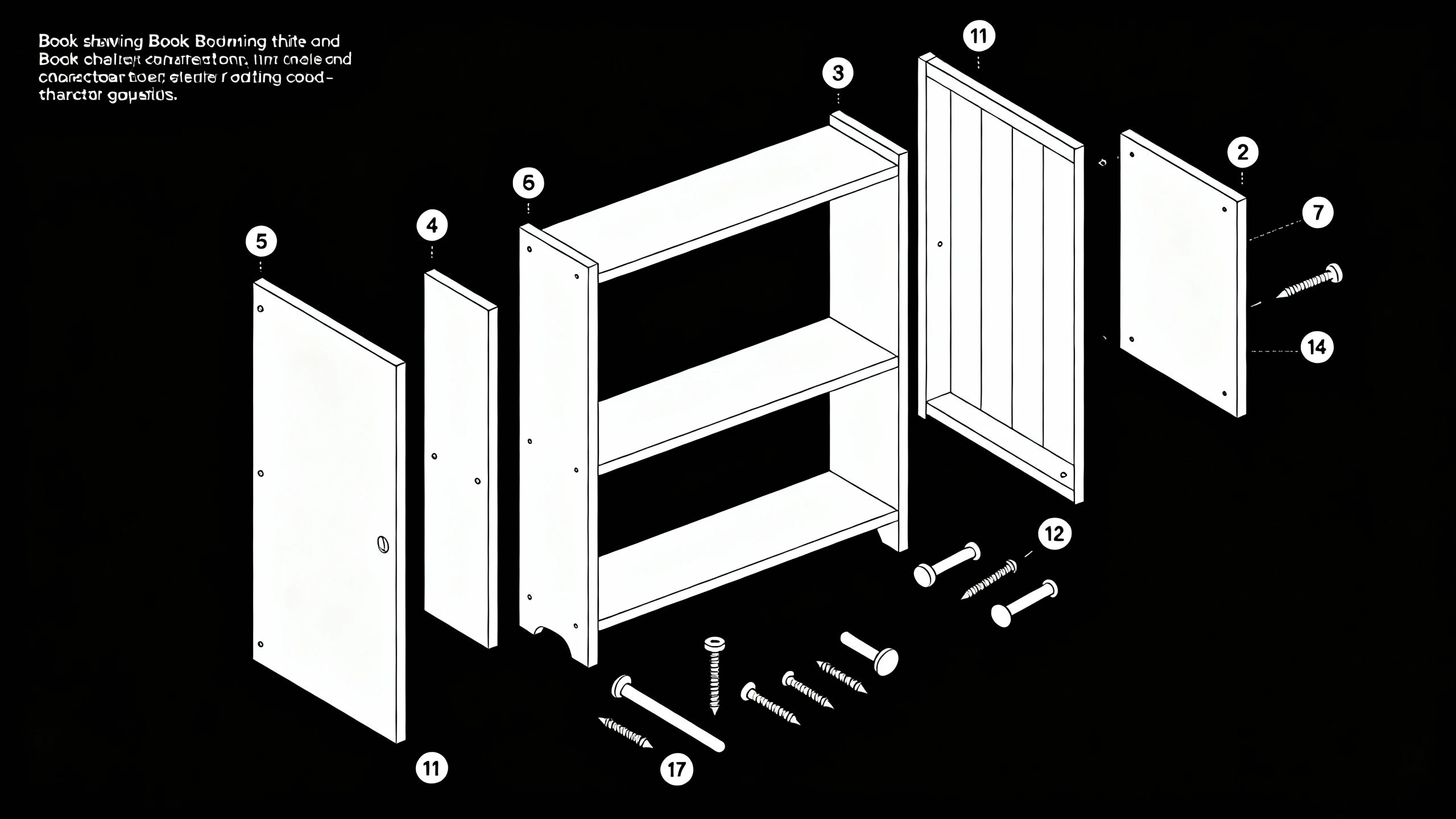
Create clear, consumer-friendly assembly guides similar to IKEA manuals. This style focuses on simplicity, clear outlines, and ease of understanding for non-experts.
- Application: Furniture assembly, toy construction kits, DIY electronics.
- Prompt: "Line art exploded view of a wooden bookshelf assembly. Isometric view. Parts: side panels, shelves, backboard, screws, dowels. Floating alignment. Black and white outline style, high contrast, clean white background, no shading. Numbered components for assembly steps."
3.2 Engineering Documentation
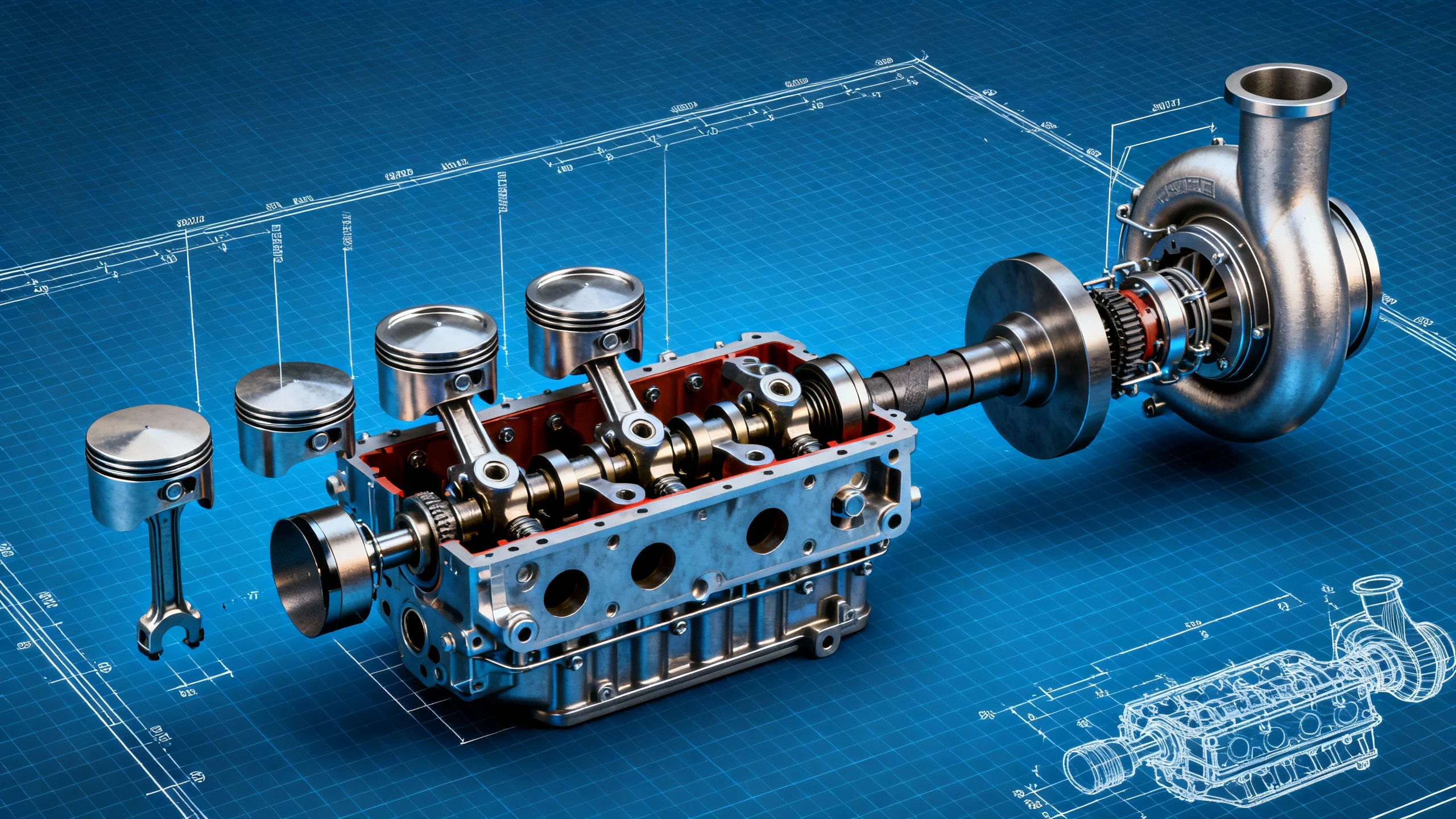
Generate detailed mechanical breakdowns for internal reports, maintenance guides, or industrial machinery documentation. This use case focuses on precision, showing complex sub-assemblies and relationship between moving parts.
- Application: Automotive repair guides, industrial pump maintenance, HVAC system schematics.
- Prompt: "Technical cutaway exploded view of a turbocharged car engine. Showing piston, cylinder head, valves, camshaft, and turbocharger unit. Metallic texture rendering, realistic shading. Parts separated along the crankshaft axis. Engineering blueprint style, blue grid background, dimension lines."
3.3 Educational Materials
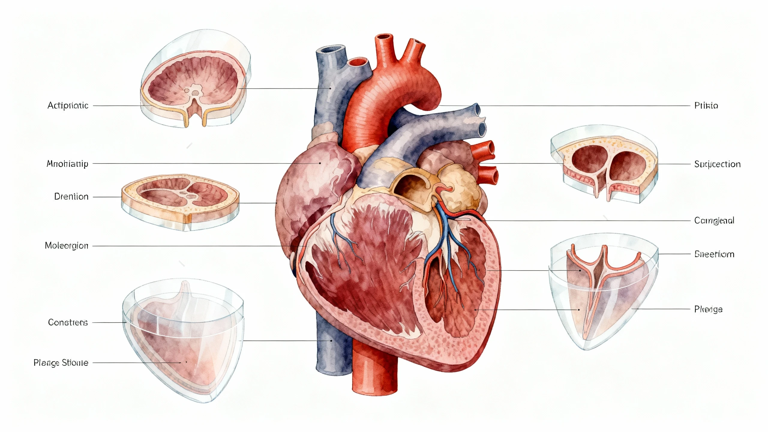
Visualize scientific concepts, biological structures, or historical artifacts for textbooks and e-learning platforms. These diagrams enhance student comprehension of internal structures that are otherwise impossible to see.
- Application: Anatomy textbooks, physics experiments, archaeology reconstructions.
- Prompt: "Biological exploded view of a human heart anatomy. Separating atria, ventricles, valves, and aorta. Floating cross-sections. Medical illustration style, soft colors, detailed labeling lines. 4k resolution, white background, educational diagram."
3.4 Patent & Technical Drawings
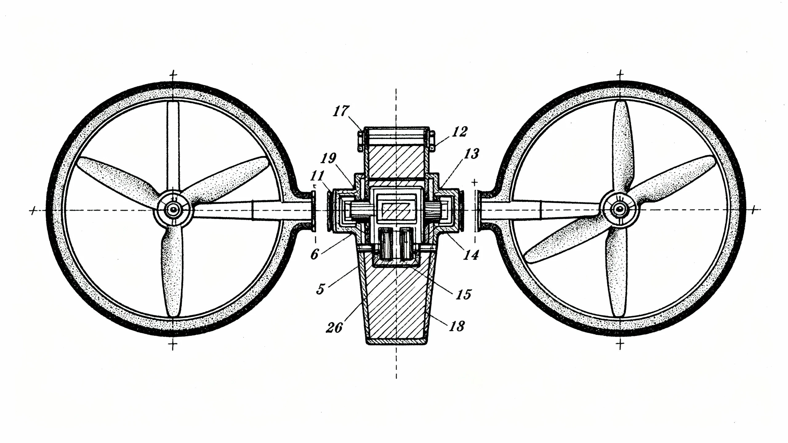
Produce formal illustrations that meet intellectual property documentation standards. These require strict adherence to line conventions, stippling for shading, and a complete lack of distracting artistic elements.
- Application: Patent filings, utility model applications, design registration.
- Prompt: "United States patent style drawing of a drone propeller mechanism. Exploded perspective view. Stippling shading, thick outer contour lines, thin inner detail lines. Component reference numbers. Black ink on white paper, official technical illustration."
4. Prompt Writing Guide
4.1 Exploded View Prompt Structure
To consistently achieve high-quality diagrams, structure your prompt logic like a CAD command. A robust prompt follows this sequence:
[Subject] + [View Type] + [Explosion Logic] + [Specific Components] + [Art Style] + [Technical Constraints].
- Template: "Exploded [View Type] of [Subject], components separated [Direction/Axis]. Including [Part List]. Style is [Art Style] with [Specific Visual traits]."
4.2 Technical Keywords
Using precise vocabulary is critical for instructing the AI to behave like engineering software rather than an art generator.
- "Exploded view": The core command for component separation.
- "Knolling": Arranging parts in parallel or at 90-degree angles flat on a surface (excellent for inventory or kit content views).
- "Cutaway": Removing outer layers to show internals without fully separating every component.
- "Wireframe": Shows the mesh structure, useful for analyzing geometry or creating futuristic HUD interfaces.
- "Schematic": Flattens the image for circuit-like or simplified functional representation.
4.3 Component Organization
You must explicitly control how parts are dispersed in space to avoid a "debris field" look.
- "Explosion Axis": Specify "Along Z-axis" (vertical stack) or "Radially" (expanding outward from a center point).
- "Spacing": Request "Wide spacing" for clarity or "Tight cluster" for compact views.
- "Trail Lines": Always request "dashed trail lines" or "guide lines" to visually connect the exploded parts back to their assembly points.
4.4 Style Variations
- Blueprint: "White lines on blue background, architectural style, grid overlay."
- Isometric Technical: "30-degree angle, parallel projection, no perspective distortion (keep lines parallel)."
- Photorealistic: "Ray-traced, metallic materials, studio lighting, ambient occlusion."
- Line Art: "Vector style, constant line weight, monochrome, high contrast."
4.5 Negative Prompts
Prevent common errors where the AI tries to be too "artistic" or messy.
- Add to Negative Prompt: "Shattered, broken glass, debris, random floating objects, text, watermark, blurry labels, uneven lines, chromatic aberration, realistic photo background, organic texture, rust, dirt."
5. FAQs
Q1: How can I create a multi-step assembly sequence for a complex product manual?
Creating a step-by-step guide requires a systematic approach since the AI generates one frame at a time.
- Deconstruction Strategy: Start by generating the "fully assembled" view. Then, for the next image, prompt for "exploded view of [outermost shell] only, revealing internal chassis."
- Sequential Prompting: Continue stripping away layers by modifying your prompt. For step 3, remove the chassis to show the battery and electronics.
- Consistency: Keep your "Seed" number consistent if possible, or use the same base styling prompts (lighting, angle, camera type) to ensure the visual style remains uniform across all steps of the manual.
- Layout: Arrange these images in a document editor, adding arrows between them to denote the progression of time or assembly order.
Q2: What is the best way to handle part numbering and labeling?
While the generator can produce "numbered components" (e.g., small circles with scribbles inside), it cannot reliably place sequential integers (1, 2, 3...) on specific parts.
- The Workflow: Prompt for "empty reference bubbles" or "leader lines with blank tags." This gives you the perfect visual placeholder.
- Post-Processing: Import the generated image into software like Adobe Illustrator, Canva, or even Microsoft PowerPoint. Overlay your own text boxes over the AI-generated bubbles. This ensures your text is legible, editable, and matches your Bill of Materials (BOM) exactly.
Q3: Can this tool replace CAD software for engineering manufacturing?
No, and it is crucial to understand the distinction.
- CAD (Computer-Aided Design): Creates mathematically precise geometric models for manufacturing (CNC, 3D printing). It defines physical tolerances.
- AI Exploded View Generator: Creates visual representations for communication. It creates "Technical Illustrations." Use the AI tool for: User manuals, marketing presentations, concept iteration, and patent draft visualizations. Use CAD for: Final manufacturing files, stress testing, and physical production. The AI tool is a "communicator," not a "constructor."
Q4: Should I use Isometric or Perspective projection?
- Isometric View: All three axes are scaled equally, and parallel lines never converge.
- Best for: Assembly instructions and technical dimensions. It allows the user to visually estimate the size of a screw relative to a panel, regardless of how "far back" it is in the image.
- Perspective View: Parallel lines converge at a vanishing point, simulating how the human eye sees depth.
- Best for: Marketing images, box art, and hero shots on websites. It looks more dramatic and realistic but can distort relative sizes, making it poor for strict technical assessment.
Q5: How do I optimize diagrams for black-and-white printing?
Many user manuals are printed on low-cost paper using black ink.
- Prompting: Use keywords like "1-bit line art," "ink drawing," "high contrast," "no shading," and "clean vector lines."
- Negative Prompting: Explicitly exclude "grey," "gradients," "shadows," and "colors."
- Post-Processing: If the image comes out with slight grey tones, apply a "Threshold" filter in an image editor to convert it to pure black and white pixels. This ensures crisp lines that won't look muddy when photocopied.
Q6: Can I use existing images or CAD screenshots as a base?
Yes, using the "Image-to-Image" (Img2Img) function is highly effective.
- Input: Take a basic screenshot of your 3D model or a photo of the product.
- Prompt: "Exploded view technical illustration of [Input Image], parts separated vertically, line art style."
- Denoising Strength: Set this parameter to roughly 0.6–0.7. This allows the AI enough freedom to "explode" the parts while keeping the general shape and identity of your original product.
Q7: What are the requirements for using these images in patent applications?
Patent offices (like the USPTO) have rigid standards:
- Black Ink Only: No greyscale or color.
- Line Quality: Lines must be crisp and uniform.
- Shading: Shading must be done via "stippling" (dots) or "hatching" (lines), not gradients.
- Prompt Strategy: "USPTO patent illustration, stippling shading, black ink on white paper, no background."
- Disclaimer: Always have a patent attorney or professional draftsperson review AI-generated images to ensure they meet the legal requirements for disclosure.
Q8: How do I visualize internal components that are blocked by outer shells?
You have two main options:
- Exploded View: Moves the outer shell away (displaces it) so you can see inside. Good for showing how things fit together.
- Cutaway View: Slices a chunk of the outer shell away (deletes it) to reveal the inside. Good for showing how the mechanism works in situ.
- Ghosting: Prompt for "semi-transparent outer shell" or "ghosted housing" to show internals through a faint outline of the exterior.
Q9: The AI keeps generating "floating debris." How do I fix this?
"Debris" or random particles often appear when the AI doesn't understand the structure.
- Fix 1: Simplify the prompt. Focus on the main sub-assemblies (e.g., "motor, battery, housing") rather than every single screw.
- Fix 2: Use Negative Prompts: "shattered, broken pieces, dust, particles, random shapes, floating rocks."
- Fix 3: Enforce an axis. "Exploded along vertical axis" helps organize the parts linearly, reducing the chance of random scattering.
Q10: Can I convert these images into Vector (SVG) formats?
The generator outputs Raster images (pixels like PNG/JPG). For professional documentation, you often want Vectors (mathematical paths like SVG/EPS) that can scale infinitely.
- Workflow: Generate a high-contrast black and white line art image -> Import into a Vectorizer tool (like Adobe Capture or online converters) -> Convert to paths.
- Benefit: You can then edit the curve of a specific line or change the line thickness in Illustrator without losing quality.
Conclusion
The Exploded View Diagram Generator represents a paradigm shift in technical documentation. By bridging the gap between complex CAD engineering and accessible visual communication, it empowers designers, engineers, and technical writers to produce professional-grade manuals in seconds. Whether you are drafting a patent, creating an IKEA-style assembly guide, or explaining a complex mechanical concept, mastering the prompts and parameters outlined in this guide will allow you to generate clear, accurate, and informative technical illustrations.